By Ronald J. Parrington, P.E., FASM
[email protected]
ESi (Engineering Systems, Inc.)
Sometimes after a component failure, a client exclaims, “We fixed that problem last year, and now it’s back again.” However, to really “fix” a problem requires: (1) identifying the failure mechanism and the cause of failure, and (2) implementing specific preventive actions. There are many ways to look at component failure. One approach is to examine the root cause. The failure root may be a physical, human, or a systemic weakness (sometimes called a latent root).
Let’s get Physical
Whether made of metals, plastics, glass/ceramics, or composites, the physical failure root generally falls into one or more of the following categories: (1) corrosion; (2) wear; (3) distortion; or (4) fracture.
- Corrosion is the environmental deterioration of a material or its properties. In a study mandated by Congress in 1999 and conducted from 1999-2001, it was found that corrosion results in approximately $276 billion in annual loss (3.1% of the gross domestic product) in the United States.
- Wear is progressive material loss due to relative motion. Although wear sounds mundane, wear failures are the most complex to analyze. The annual cost of wear rivals that of corrosion.
- Distortion is deformation that prevents a component from performing its intended function. Distortion is rarely the subject of a failure investigation, because you don’t need a rocket scientist or a rock-star failure analyst (like the author) to determine if the component has been overloaded or under-designed.
- Fracture occurs when a component breaks into two or more fragments. It is the most serious type of failure, because fracture can occur without warning, and have catastrophic consequences.
For each of these physical causes of failure, there are numerous potential failure mechanisms. For example, when a component fractures in a brittle manner but is made of a normally ductile material, the possible failure mechanisms are high cycle fatigue or one of many types of material embrittlement. Extensive materials testing may be necessary to definitively identify the failure mechanism.
To Err is Human
Human causes of failure (also known as “roots”) are simply component failures that result from human error. Design errors are the most common human cause of failure. The table below lists the results from one study which showed that the designer was most often responsible for component failures caused by humans. My favorite human root is Supervisory Contribution. “The boss told me to do it and that’s why it failed.” Note that the percentages in the table total over 100%. When something fails, there’s plenty of blame to go around.
| Human Root Cause of Failure | % |
| Design | 59 |
| Maintenance | 38 |
| Operating | 24 |
| Installation | 16 |
| Manufacturing | 12 |
| Supervisory Contribution | 10 |
Systemic Roots
Systemic or latent roots include failures due to inadequate quality control, training, procedures, etc.
Point of Origination
Another way to look at component failure is to address the point in the product life cycle (design, manufacturing, service, or material) when the cause of failure originated. In the following study, improper material selection was identified as the most common cause of failure. For example, if the designer selected ultra-high-molecular-weight polyethylene (UHMWPE) and the UHMWPE component failed, the failure is far more likely due to the designer’s choice of material than due to a defect in the material. While it might be tempting to say that “there is something wrong with this material,” the material most likely failed because it was not appropriate for the design, manufactured inadequately, or abused in service. Defects in the material itself are rarely the cause of failure (only 2% in this study).
| Root Cause of Failure | % |
| Improper Material Selection | 38 |
| Fabrication Defects | 15 |
| Faulty Heat Treatment | 15 |
| Mechanical Design Fault | 11 |
| Unforeseen Operating Condition | 8 |
| Inadequate Environmental Control | 6 |
| Improper Inspection/Quality Control | 5 |
| Material | 2 |
Tools of the Trade
Materials testing, product testing, failure analysis, and engineering analysis are critical to identifying the failure mechanism, cause of failure, and preventive actions. Standard tools of the trade include visual examination, optical microscopy, scanning electron microscopy, mechanical testing (tensile properties, hardness, etc.), chemical analysis, thermal analysis, stress analysis, fractography, and fracture mechanics. The following examples show how some of these tools are used as part of an engineering investigation.
Example 1 – Fractured Titanium Screws
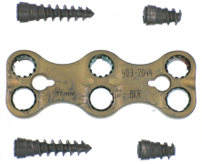
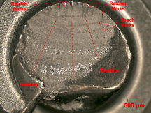
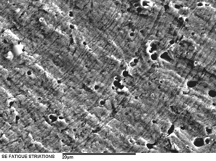
In Example 1 visual examination and scanning electron microscopy were used to investigate fractured titanium screws used in a fixation device for a broken bone. Macroscale examination of the fracture surface revealed that the failure mechanism is multiple-origin, unidirectional, bending fatigue. Fatigue is an important and common progressive fracture mechanism due to cyclic stresses. On the microscale, using a scanning electron microscope, the observation and measurement of fatigue striations confirm that fatigue is the failure mechanism and allowed the crack growth rate to be calculated. Fatigue striations are microscopically visible, semi-elliptical or elliptical lines on a fatigue fracture surface that mark successive positions of the advancing crack front with each cycle of stress.
Example 2 – Cracked and Leaking Implantable Drug Pump
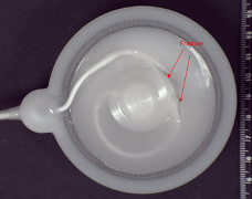
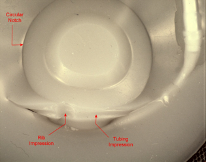
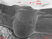
Example 2 shows the diaphragm of a silicone rubber implantable drug pump that cracked at the point where the silicone rubber tube interfaces with a notch-like design feature. A room temperature vulcanizing (RTV) rubber repair was found at the fracture origin. The fracture occurred as a result of monotonic overload of a weak adhesive joint between the tube and the diaphragm. Applied (operating) and residual (thermal and cure-related) stresses drove the failure. Macroscopically, the fracture surface appears relatively smooth and featureless, as expected for an elastic fracture. Microscopically, the fracture surface exhibits areas of smooth, featureless fracture morphology, and areas checkered with micro-cracking. The network of micro-cracking is attributed to high constraint and triaxial (radial, hoop and axial) tensile stresses on the plane of fracture.
About Engineering Systems Inc. (ESi)
ESi is a full-service engineering and investigative analysis firm with 17 locations and well-equipped laboratories conveniently located across the United States, including in Plymouth, MN. ESi has over 200 engineers and scientists representing nearly all disciplines. Our services include materials and product testing, failure analysis, regulatory support, and engineering consulting services.
For more information, visit https://www.engsys.com/areas-of-expertise/products/medical-devices and https://www.engsys.com/areas-of-expertise/industry-support-services/regulatory-pharmaceutical-medical-devices
For quotations please contact Ron Parrington (https://www.engsys.com/consultants/ronald-j-parrington) at (763) 447-2752 or [email protected].